Please Note: Prices subject to change without notice
Cat1


 π
π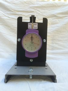
 SUMMARY:
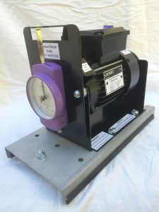
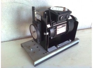
This unit can be coupled on the Machine Bed Plate(091002-A) using a Rubber Coupling (090128-3) to all motors in the range to measure motor Locked-Rotor &/or output torque or used as a variable controlled load
Field excitation requires a variable 0 >24 or 0 >36V dc power supply
To determine the correct torque gauge setting
Calculate motor's full-load output torque as follows
From Power equation: P = 2πnT/60
where
P = motor output power in Watt (read from the motor's nameplate)
n = motor full load speed (read from the motor's nameplate)
T = the motor's output torque in Newton Meter (Nm) can be calculated using the following calculation
Transposition of the above Power equation
Then
The output Torque: T = 60P/2πn in Nm
This is the torque setting the Dynamometer is to be loaded/adjusted to, by varying it's field excitation
SUMMARY:
This unit can be coupled on the Machine Bed Plate(091002-A) using a Rubber Coupling (090128-3) to all motors in the range to measure motor Locked-Rotor &/or output torque or used as a variable controlled load
Field excitation requires a variable 0 >24 or 0 >36V dc power supply
To determine the correct torque gauge setting
Calculate motor's full-load output torque as follows
From Power equation: P = 2πnT/60
where
P = motor output power in Watt (read from the motor's nameplate)
n = motor full load speed (read from the motor's nameplate)
T = the motor's output torque in Newton Meter (Nm) can be calculated using the following calculation
Transposition of the above Power equation
Then
The output Torque: T = 60P/2πn in Nm
This is the torque setting the Dynamometer is to be loaded/adjusted to, by varying it's field excitation
 Price:
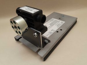
 The water pump module has been developed for use as a hydraulic ‘motor-load’
Any of the ac or dc motors may be used as the prime mover
The Module enables Output-Power calculations using hydraulic pressure head measurement and flow rates
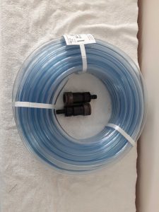
The Pumps Inlet & Outlet are standard 3/4″-14 BSP (i.e standard garden Tap thread) This allows ‘any-brand’ of standard garden hose accessories to be fitted to the pump
A separate stand-alone Hose-Kit is also available (Product PHK-001: 30m x 12mm clear Plastic Vinyl tubing & click-on hose fittings)
The water pump module has been developed for use as a hydraulic ‘motor-load’
Any of the ac or dc motors may be used as the prime mover
The Module enables Output-Power calculations using hydraulic pressure head measurement and flow rates
The Pumps Inlet & Outlet are standard 3/4″-14 BSP (i.e standard garden Tap thread) This allows ‘any-brand’ of standard garden hose accessories to be fitted to the pump
A separate stand-alone Hose-Kit is also available (Product PHK-001: 30m x 12mm clear Plastic Vinyl tubing & click-on hose fittings)
 Click on to down load instructions > 200704 Pump instructions
HOW TO USE THIS PUMP
MOST IMPORTANT:
ONLY OPERATE IN A CLOCKWISE DIRECTION (Viewed on coupling)
ALWAYS DOUBLE CHECK THE CORRECT DIRECTION OF MOTOR ROTATION “PRIOR TO COUPLING THE MOTOR TO THE PUMP”
ENSURE SUCTION HOSE IS ALWAYS IMMERSED. BOTH BEFORE STARTING THE PUMP AND WHILE IN USE
WARNING
DO NOT LET THE PUMP RUN DRY
Turn off immediately when container is drained (pump becomes inoperable if run dry, and doing so voids warranty)
Not suitable for drinking water
Do not use with flammable or corrosive materials
MAX. PUMP RATINGS (Water (H20))
RPM : 3000
Output : 20 lt/min (0.33 lt.s-1)(0.33 kg.s-1)
Pump height : 13.7 m
Self Priming : 2.75 m max.
Click on to down load instructions > 200704 Pump instructions
HOW TO USE THIS PUMP
MOST IMPORTANT:
ONLY OPERATE IN A CLOCKWISE DIRECTION (Viewed on coupling)
ALWAYS DOUBLE CHECK THE CORRECT DIRECTION OF MOTOR ROTATION “PRIOR TO COUPLING THE MOTOR TO THE PUMP”
ENSURE SUCTION HOSE IS ALWAYS IMMERSED. BOTH BEFORE STARTING THE PUMP AND WHILE IN USE
WARNING
DO NOT LET THE PUMP RUN DRY
Turn off immediately when container is drained (pump becomes inoperable if run dry, and doing so voids warranty)
Not suitable for drinking water
Do not use with flammable or corrosive materials
MAX. PUMP RATINGS (Water (H20))
RPM : 3000
Output : 20 lt/min (0.33 lt.s-1)(0.33 kg.s-1)
Pump height : 13.7 m
Self Priming : 2.75 m max. 
Price:
Note: for optimum performance at least one(1) Field Rheostat (1550-0-100R) should be purchased with this machine.
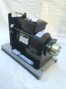
24.0Vdc, 60W Motor or Generator – may be connected for shunt, Series or Compound operation, and Ward-Leonard speed control dc Machine efficiency
This dc machine has eleven(11) leads terminated at the terminal box with 4mm diameter sockets enabling the machine to be externally connected as:- Series Motor: 210204 W dc machine CCT Diag .
- Shunt Motor: a. Self Excited; 210204 V dc machine CCT Diag b. Separately Excited: 210204 U dc machine CCT Diag .
- Compound Motor: a. Cumulative Compound : (Long Shunt :210204 X dc machine CCT Diag )(Short Shunt :210204 Y dc machine CCT Diag)( Separately Excited :210204 Z dc machine CCT Diag) b. Differential Compound 130521-2-dc-machine-connections .
- Series Generator:171111-B CCT Diag .
- Shunt Generator: a. Self Excited :171111-A CCT Diag b. Separately Excited : 171111-D CCT Diag .
- Compound Generator: a. Cumulative Compound : (Short Shunt : 171111-C CCT Diag)(Separately Excited : 171111-E CCT Diag) b. differential Compound .
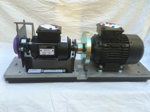
- “Ward-Leonard” Speed Control 120829 Circiut Diagram – Ward-Leonard Combining two dc machines, a prime mover motor (63-1-L8240-A) and the special field rheostat (2G25-0-300R) the Ward-Leonard method of speed control can be demonstrated.(refer above link) .
- ac Universal/Series Motor: Universal ac Series Motor As the field iron circuit is fully laminated the machine can be connected, using 25% of the Series Field winding to demonstrate a single phase ac Series/Universal motor. i.e. the motor has the inherent ability to operate on either an ac or dc supply. .
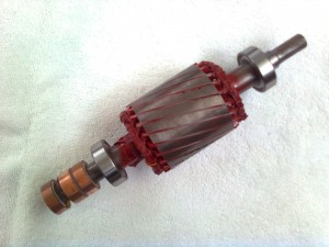
- HANDS-ON – Torque – Physical evaluation: With care, the relatively large outside diameter metal coupling (090202-14), attached to the motor’s output shaft, may be gripped by hand by the student in the stalled (locked-armature) position so that the student can physically feel the ‘very-high’ starting torque developed by dc motors, as predicted in the theory. .
- Auxiliary Starting/Control Gear: . 2415-0-T001: 0>24V, 15A, dc Regulated Power Supply This is recommended minimum power supply for optimum performance in the dc motor mode. or an equivalent power supply of equal or greater output . 1550-0-100R: Shunt Field Rheostat Required to demonstrate the effect on the armature RPM by varying the shunt field current/flux in the motor mode.


- Capacitor “START” motor, Capacitor “RUN” (2 or Dual Capacitor motor) 180420-1Cap S&R CCT Diag.Issue Apdf
- Capacitor “Start” Motor 180420-2 Cap S CCT Diag.Issue Apdf
- Capacitor ”Start” – Adjustment of Starting Torque using Capacitor External Bank 71-1-CT001 71-1-CT001 CapStart Torque Diag
- 140306 circle diagram issue A
- Capacitor “RUN” motor or Permanent-Split-Capacitor(PSC);180420-3 Cap R CCT Diag
- Also, as both the Main(or Run) and Auxiliary(or Start) winding are wound with very similar numbers of turns & wire gauge, the motor may be connected to operate as a “REVERSING” PSC motor.180420-4 Cap R Reverse CCT Diag
- Power factor (pf) correction in-conjunction with Capacitor External Bank 71-1-Cpf001 71-1-Cpf001 CapStart pf correction Diag
- pf correction table
- “Very-High” starting torque of the capacitor “START” motor; and
- “Low” starting torque of the capacitor “RUN” motor.
- In a “Separated-Extra-Low-Voltage”(SELV) supply. i.e. between to actives;
- The use of a 415 Vac ‘single’ phase condenser fan motor in a 3ph, domestic air conditioners (phase to phase) to eliminate the need for a neutral conductor; or
- The use of a 415 Vac ‘single’ phase cooling fan motor in industrial welders. This enables the welder to be plugged into any Common/Normal standard ‘4 pin’(3ph+E) 3 phase outlet without concern of different phase sequences which would cause a 3ph motor to rotate in the wrong direction. As well as again, eliminating the need for a neutral conductor which would require the use of a “NOT-Common” 5 pin(3ph+N+E) 3ph plug & socket outlet


Price on application
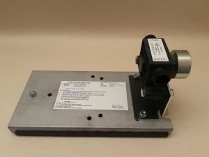
This is the standard 3ph, 4 pole SCIM (71-3-L004) fitted with a “Rotary Encoder”
Final price dependent on the make and model of rotary encoder specified by the customer, whether the rotary encoder is supplied by eme or the customer
Rotary encoder pictured on this motor is a:
Omron
type: E6B2-CWZ6C
Resolution: 600P/R – 5 to 24 Vdc
Please note: Rotary encoder can be fitted to other machines in the range if required
Again, price on application.


- High speed operation (2 pole)2&4 pole Dharlander
- Low speed operation (4 pole)

- Synchronous Generator (Alternator)
- Synchronous Motor – Self starting(Induction)
- Synchronous Capacitor


 SET-UP
Connect the six SCIM terminals to the six motor terminals on the starter switch (Note, in the correct sequence i.e. U1 to U1, V1 to V1 etc.)
Connect the external 3 phase 41.5V supply the the Input supply terminals on the starter
To best observe the operation of each starting method, connect a 5A Ammeter in series with Line 1(A1), and a second 5A ammeter in series with motor lead U1 (A2).
And replace the standard metal coupling (090206-614) with the Inertia Wheel (130712-614)
SET-UP
Connect the six SCIM terminals to the six motor terminals on the starter switch (Note, in the correct sequence i.e. U1 to U1, V1 to V1 etc.)
Connect the external 3 phase 41.5V supply the the Input supply terminals on the starter
To best observe the operation of each starting method, connect a 5A Ammeter in series with Line 1(A1), and a second 5A ammeter in series with motor lead U1 (A2).
And replace the standard metal coupling (090206-614) with the Inertia Wheel (130712-614)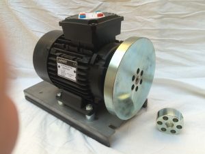 .
.
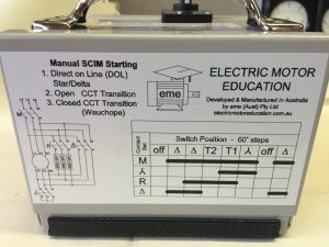
Description of Starting Methods
.
1. D.O.L operation:
a. Rotate switch from ‘OFF’ in a clockwise(CW) direction one step to Δ (delta).
b. Note the currents and time (in seconds) for the Inertia Wheel to accelerate to full speed.
c, To switch off rotate switch Anti-clockwise(ACW) one step to ‘OFF’
.
2. Star/Delta – OPEN Circuit Transition operation:
a. Rotate ACW one step to ‘Y’ (Star).
b. Note the start Star connection currents (i.e. 1/3 the DOL value).
c. By observation of both the Inertia Wheel & Ammeters,
d. note the time (in seconds) for the Inertia wheel to accelerate to full speed.
e. When the current has been observed to fall to the minimum value, rotate the switch quickly CW two(2) steps to Δ (delta).
In this process it will be observed that the motor is disconnected from the line (as it passes through the ‘OFF‘ position) in order for the motors connections to be changed from Star to Delta.
i.e. ‘Open’ circuit transition’.
f. To switch off, rotate switch ACW one step to ‘OFF’
.
3. Star/Delta – Closed Circuit Transition (Wauchope) operation: a. Rotate the switch ACW one step to ‘Y'(star).
b. By observation of both the Inertia Wheel & Ammeters note the time (in seconds) for the Inertia Wheel to accelerate to full speed.
c. When the current has been observed to fall to the minimum value, relatively quickly rotate the switch ACW two steps through T1 to T2. IMPORTANT, PLEASE NOTE:
Step T1 is the first stage of the transition from Star to Delta. It is here a set of 3 relatively low resistance resistors are connected both in Star and in parallel with the motor,
Note, the resistors are connected across the full voltage and thus will be required to dissipate a large amount of heat.
In practice this is a momentary transition step and the heat loss is negligible.
Thus the student must be instructed to only dwell at step T1 long enough to observe Ammeter readings.
A Prolonged stay at switch position T1 may cause the resistors to overheat and burn-out.
d. When the switch is at position T2 the star point is opened, Thus without disconnecting the motor from the line the motor winding and resistors are connected in Series and in Delta (i.e.a Delta connected primary resistance starter connection).
e. Rotating the switch ACW one more step to Δ (delta) short circuits the series resistors, thus connecting the motor in Delta across the full voltage with out disconnecting the motor from the supply.
i.e. ‘Closed Circuit Transition.
f. To switch the motor off rotate the switch ACW two steps to ‘OFF’.
.
.
Description of Starting Methods
.
1. D.O.L operation:
a. Rotate switch from ‘OFF’ in a clockwise(CW) direction one step to Δ (delta).
b. Note the currents and time (in seconds) for the Inertia Wheel to accelerate to full speed.
c, To switch off rotate switch Anti-clockwise(ACW) one step to ‘OFF’
.
2. Star/Delta – OPEN Circuit Transition operation:
a. Rotate ACW one step to ‘Y’ (Star).
b. Note the start Star connection currents (i.e. 1/3 the DOL value).
c. By observation of both the Inertia Wheel & Ammeters,
d. note the time (in seconds) for the Inertia wheel to accelerate to full speed.
e. When the current has been observed to fall to the minimum value, rotate the switch quickly CW two(2) steps to Δ (delta).
In this process it will be observed that the motor is disconnected from the line (as it passes through the ‘OFF‘ position) in order for the motors connections to be changed from Star to Delta.
i.e. ‘Open’ circuit transition’.
f. To switch off, rotate switch ACW one step to ‘OFF’
.
3. Star/Delta – Closed Circuit Transition (Wauchope) operation: a. Rotate the switch ACW one step to ‘Y'(star).
b. By observation of both the Inertia Wheel & Ammeters note the time (in seconds) for the Inertia Wheel to accelerate to full speed.
c. When the current has been observed to fall to the minimum value, relatively quickly rotate the switch ACW two steps through T1 to T2. IMPORTANT, PLEASE NOTE:
Step T1 is the first stage of the transition from Star to Delta. It is here a set of 3 relatively low resistance resistors are connected both in Star and in parallel with the motor,
Note, the resistors are connected across the full voltage and thus will be required to dissipate a large amount of heat.
In practice this is a momentary transition step and the heat loss is negligible.
Thus the student must be instructed to only dwell at step T1 long enough to observe Ammeter readings.
A Prolonged stay at switch position T1 may cause the resistors to overheat and burn-out.
d. When the switch is at position T2 the star point is opened, Thus without disconnecting the motor from the line the motor winding and resistors are connected in Series and in Delta (i.e.a Delta connected primary resistance starter connection).
e. Rotating the switch ACW one more step to Δ (delta) short circuits the series resistors, thus connecting the motor in Delta across the full voltage with out disconnecting the motor from the supply.
i.e. ‘Closed Circuit Transition.
f. To switch the motor off rotate the switch ACW two steps to ‘OFF’. 
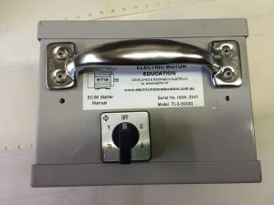
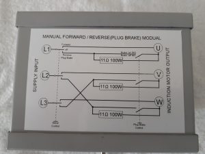 This is a stand alone module is used in conjunction with the 3 phase Squirrel Cage Induction motor(SCIM) (Product Code: 71-3-L004)
The Starter can be used as a “Manual 3 phase Forward/Reverse switch”, &/or
to manually demonstrate “Plug Braking”, in either of two modes
This is a stand alone module is used in conjunction with the 3 phase Squirrel Cage Induction motor(SCIM) (Product Code: 71-3-L004)
The Starter can be used as a “Manual 3 phase Forward/Reverse switch”, &/or
to manually demonstrate “Plug Braking”, in either of two modes
- Plug Braking with Full Voltage(i.e. Max. Braking Current), or
- Plug Braking with current limiting resistance

 For best braking effect the 3 phase SCIM should be fitted with the Inertia Wheel Coupling (Product Code: 130712/614)
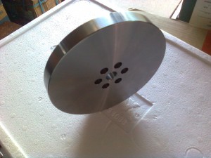 Click to view Circuit Diagram:180828-A Dynamic Brake Circuit Diagram
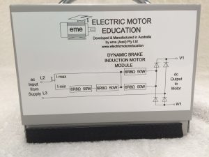
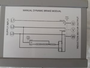 For the Automated version, see Product Code 71-10-DB002
For best braking effect the 3 phase SCIM should be fitted with the Inertia Wheel Coupling (Product Code: 130712/614)
Click to view Circuit Diagram200607 Dynamic BrakeMANUAL ac ModuleCCT
For the Automated version, see Product Code 71-10-DB002
For best braking effect the 3 phase SCIM should be fitted with the Inertia Wheel Coupling (Product Code: 130712/614)
Click to view Circuit Diagram200607 Dynamic BrakeMANUAL ac ModuleCCT 


- Maximum Starting Torque: By increasing the resistance of the secondary circuit, by adding extra external resistance into the secondary circuit, so that the secondary resistance in ohms equals the secondary inductive reactance in ohms, the motor can produce it’s maximum torque at start (i.e. R=XL), and by the addition of suitable metering, it can be shown that the Primary starting current is reduced
- Speed Control: By adjusting the value of added external secondary resistance, under load, the ability to gain speed control at constant torque is achieved. Again, by the addition of suitable metering, it can be shown that whilst the Primary input power and current remain constant throughout the speed range (at constant torque) the excess secondary energy is dissipated as heat through the external secondary rheostat resistance.
 Price:
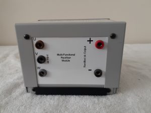
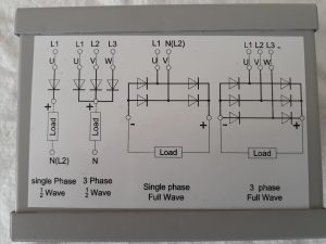
This is a multi-functional rectifier which enable the demonstration of:
Half wave single phase
Full wave single phase
Half wave 3 phase
Full wave 3 phase rectification within the one module
Price:
This is a multi-functional rectifier which enable the demonstration of:
Half wave single phase
Full wave single phase
Half wave 3 phase
Full wave 3 phase rectification within the one module
 190914 Multi-Functional Rectifyer Module
Price on Application
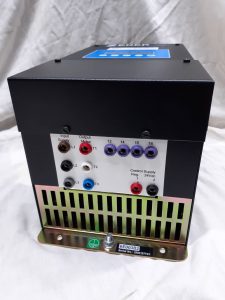
This a Heavy Duty NON-Regulated, dc power supply
Input:
240 Vac, 50Hz single phase
Output:
0>30 Vdc for light loads
0>24 Vdc, 30 A, at 50% duty


 Cost Price :
Special: SMARTSTARTER 6000, 41.5 Vac, 3A starter
For use with ELV 3 Phase Motor (SCIM) Product Code 71-3-L004
Refer operation manual: http://www.zener.com.au/images/imi0042.pdf
Cost Price :
Special: SMARTSTARTER 6000, 41.5 Vac, 3A starter
For use with ELV 3 Phase Motor (SCIM) Product Code 71-3-L004
Refer operation manual: http://www.zener.com.au/images/imi0042.pdf 

 Power Supply – Single phase to 3 phase Rotary Phase Change Converter (1>3ph)
Rating : 500 VA
Input: This unit Plugs into a standard 3 pin, 10A, 240V Low-Voltage(LV), 50Hz Single Phase, Power Outlet, or General Purpose Outlet(GPO)
Output: 3 phase, 4 wire(3+N), 41.5/24.0V Extra-Low-Voltage(ELV), 6.6A/phase, 50Hz (isolated) via 4 x 4mm banana terminals
The unit uses a 3 phase idler motor, in conjunction with capacitance, inductance and microprocessor technology to directly produce a 3 phase output having a relatively clean Analogue Sine Wave, low in harmonics. Unlike Inverters which firstly rectify the incoming energy before chopping/switching the resulting dc link into a simulated, digitised, synthesised, harmonic laden sine wave 3 phase look alike output
This power supply has been designed for use in rooms not fitted(wired) with a 415V 3 phase power supply or outlet
The unit enables any room/area fitted with a standard Low Voltage(LV)240V single phase 3 pin, 10Amp power outlet (GPO) to run 3 phase ELV electrical subjects/modules
The unit will support both single & 3 phase, inductive, capacitive and resistive loads
Thus eliminating the need for traditional, expensive, high cost, dedicated, limited use, electrical machine laboratories fitted/wired with the higher, potentially more hazardous, 415Volt, 3 phase outlets
Approx. Size: 430x355x440mm .
Overall weight approx. 34kg
Fitted with 2 carrying handles
Power Supply – Single phase to 3 phase Rotary Phase Change Converter (1>3ph)
Rating : 500 VA
Input: This unit Plugs into a standard 3 pin, 10A, 240V Low-Voltage(LV), 50Hz Single Phase, Power Outlet, or General Purpose Outlet(GPO)
Output: 3 phase, 4 wire(3+N), 41.5/24.0V Extra-Low-Voltage(ELV), 6.6A/phase, 50Hz (isolated) via 4 x 4mm banana terminals
The unit uses a 3 phase idler motor, in conjunction with capacitance, inductance and microprocessor technology to directly produce a 3 phase output having a relatively clean Analogue Sine Wave, low in harmonics. Unlike Inverters which firstly rectify the incoming energy before chopping/switching the resulting dc link into a simulated, digitised, synthesised, harmonic laden sine wave 3 phase look alike output
This power supply has been designed for use in rooms not fitted(wired) with a 415V 3 phase power supply or outlet
The unit enables any room/area fitted with a standard Low Voltage(LV)240V single phase 3 pin, 10Amp power outlet (GPO) to run 3 phase ELV electrical subjects/modules
The unit will support both single & 3 phase, inductive, capacitive and resistive loads
Thus eliminating the need for traditional, expensive, high cost, dedicated, limited use, electrical machine laboratories fitted/wired with the higher, potentially more hazardous, 415Volt, 3 phase outlets
Approx. Size: 430x355x440mm .
Overall weight approx. 34kg
Fitted with 2 carrying handles 


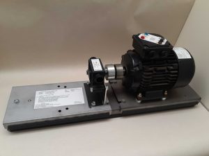
 This is a simpler, smaller, stand alone motor and inertia load arrangement.
Unlike the Betts Inertia wheel which is a separate load requiring both it and the drive unit to be mounted on a machine bed plate for coupling
It will be noted that this inertia wheel also has the 6 drive hole for accepting the rubber coupling (code 090128-3) thus still enabling the coupling of 2 machines on a machine bed plate. The Inertia wheel in this arrangement now acts as and can demonstrate a flywheel action
When fitted to any of the ac or dc motors the wheel’s inertia enables the test set-up and instruments to more clearly demonstrate the functional difference between different starting and braking methods
The wheel weighs 2.63 kg
mass: m = 0.268 kg
Moment of inertia: J = 7.54 x 10⁻⁴ kgm2
Outside diam. = 150mm
This is a simpler, smaller, stand alone motor and inertia load arrangement.
Unlike the Betts Inertia wheel which is a separate load requiring both it and the drive unit to be mounted on a machine bed plate for coupling
It will be noted that this inertia wheel also has the 6 drive hole for accepting the rubber coupling (code 090128-3) thus still enabling the coupling of 2 machines on a machine bed plate. The Inertia wheel in this arrangement now acts as and can demonstrate a flywheel action
When fitted to any of the ac or dc motors the wheel’s inertia enables the test set-up and instruments to more clearly demonstrate the functional difference between different starting and braking methods
The wheel weighs 2.63 kg
mass: m = 0.268 kg
Moment of inertia: J = 7.54 x 10⁻⁴ kgm2
Outside diam. = 150mm

Note: minimum order quantity 15 units
This coupling is used to join two(2) metal couplings (090206-xx) or the Inertia Wheel(130712-614) when clipping two(2) machines together on the Machine Bed Plate (091002-A)
This coupling is fully interchangeable and compatible with the former Betts metal & rubber couplings


- Price:

Price on application
Extra-Low-Voltage, Low-Voltage & communications distribution centre for wiring practical cubicles or panels
The Low voltage supply is segregated by a continuous internal barrier from the Extra-Low-Voltage & communications supplies within the box
Size of Distribution box: 250 x 250 x 75
Material: sheet-metal
Finish: Powder coated
Other arrangements. configurations &/or sizes can be designed and quoted on request
- Price:


